IC-controlled LED (Revisited)
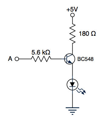
In my previous post about this topic from five years ago, my circuit had the LED hooked up to the emitter of the transistor:

I’m not sure why I did it this way; the “Using a transistor as a switch” section of that amazing page about transistors clearly shows the load as being above the collector, with the emitter attached directly to ground. Moreover, attaching the emitter to ground makes it possible to drive multiple LEDs independently with an IC containing multiple transistors with a common emitter such as the ULN2003A, which appears to be a very common source of NPN transistors in TTL and CMOS designs.
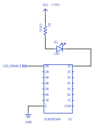
Here’s another attempt, using that IC:

This circuit assumes that the LED has a forward voltage drop of 1.8 V, and
operates at 20 mA. LED_ENABLE is the output of a logic IC running at 5 V. See
this StackExchange question for discussion.
A few things to note:
-
We can directly connect the logic IC output to the base pin, because the ULN2003A has an internal current-limiting resistor for the base.
-
The resistor value is chosen by dividing the voltage across the resistor (5 V for the supply, minus 1.8 V for the LED, minus 0.9 V for the collector-emitter voltage at saturation) by the LED current.