Power-On Reset
In order to ensure that everything is in a well-defined state after power-up, you often need to generate a reset signal that lasts at least until the power supply is stable (and maybe for a little while longer).
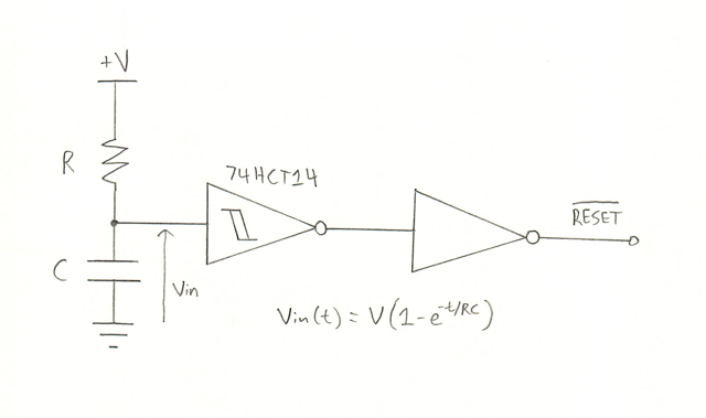
The circuit below accomplishes this using an inverter gate with a Schmitt trigger:

This generates an active low reset. (The second inverter can also be from the 74HCT14 IC, and can obviously be removed to make an active high reset signal.)
Once the voltage source ramps up, the capacitor and therefore the input to the inverter is charged according to the equation in the image. (If the ramp-up of the voltage source is slow, this isn’t accurate; if it’s particularly slow the capacitor can even charge at nearly the same rate as the ramp-up.) Once it reaches the upper threshold voltage of the Schmitt trigger the output flips and the reset signal goes away.
The graph in the datasheet for the 74HCT14 shows an upper threshold voltage of ~2.8 V when the power supply is 5 V. Re-arranging the equation shows that RC should be approximately t / 0.82. So if you wanted a 100 ms reset time for example, you could use a 4.7 µF capacitor and a 25 kΩ resistor.